办公室电话:
(022)27405110
销售部电话:
(022)27403647
EMAIL:
tjdxcbsyxzrgs@163.com
企业荣誉
ENGLISH
首页
关于我们
出版社简介
领导分工
组织机构
我要投稿
客服中心
图书中心
资源下载
数字服务
党建园地
新闻中心
联系我们
图书中心
2024室内设计论文集
了解更多>>
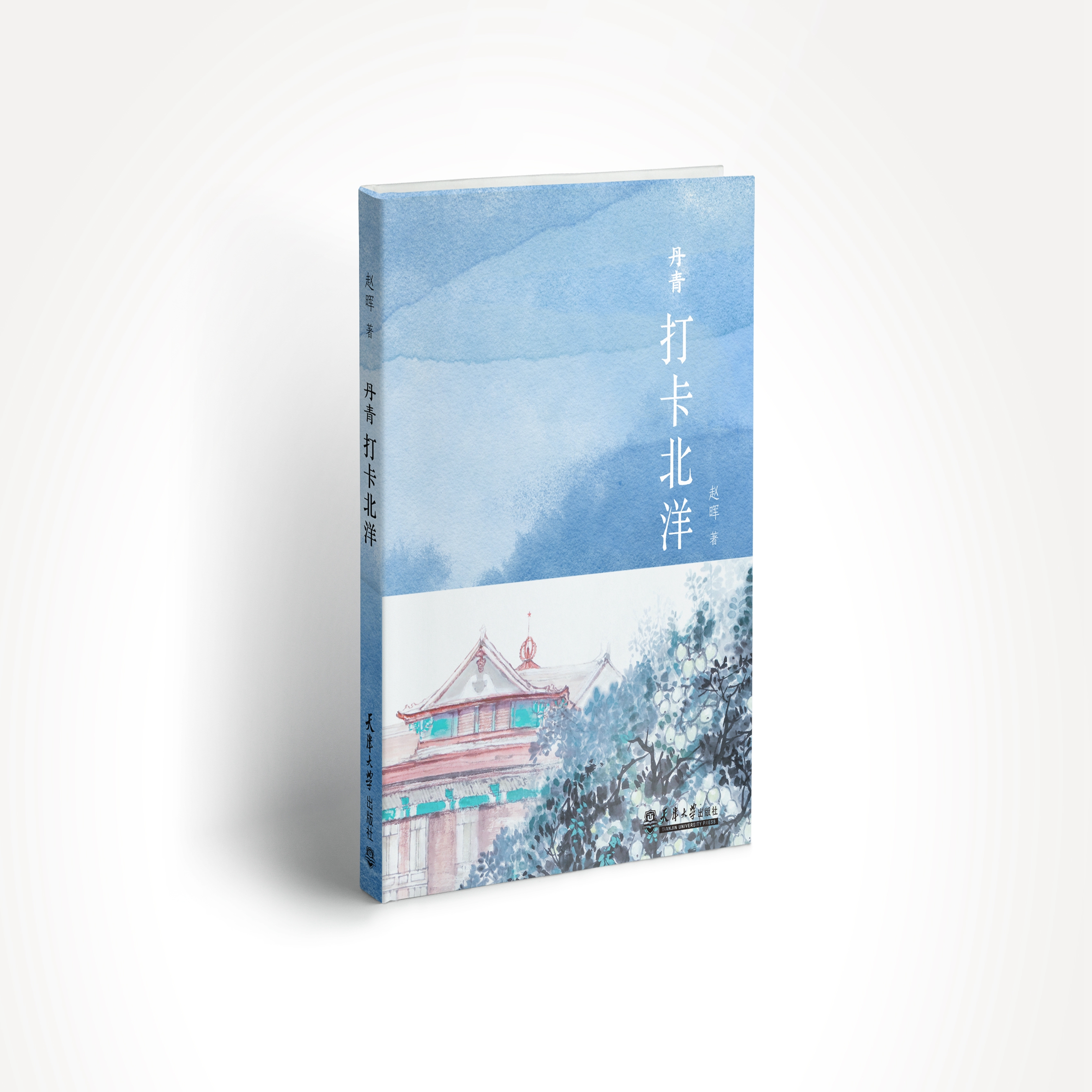
庆祝天大建校130周年新书出版
近日,天津大学出版社推出《丹青打卡北洋》,让更多人了解中国第一所现代大学——天津大学的发展历程。
了解更多>>
Key titles
强力推荐
电子技术基础与技能
冯璐 韩艳茹 焦宝玉
普通话与职业口语训练
万能
建筑CAD
黄瑶
固定消防设施
徐方
国学经典选读
李清彬
直播营销与运营
张蕊, 张磊 ,王冲
经济法
李昕一,闫玉苹,李巍,赵妍,牛丽天
中国文学典籍英译
刘蕾,耿艳梅,多津玲
内燃机原理实验
刘海峰 郑尊清 主编;许之兴 王同金 副主编
零基础创建基于Python和Flask的深度学习预测网站
程翔、刘子、严帅、喻庆志、袁海芹
行书技法
郝略韬
区块链与信息安全
蔡雪莲 余棉水 鲁庆
汽车底盘构造与维修
王龙,孙云明主编 周建江,莫尔登,赵永奕 副主编
高效对话大语言模型
王凯峰,孙之琳
图形创意
王艺湘,冯紫薇
2024室内设计论文集
中国建筑学会室内设计分会
美术鉴赏
聂涛
丹青打卡北洋
赵晖
仰望星空 脚踏实地:高校思想政治理论课魅力课堂
邹礼玉 著
公平理论视角下的企业和谐劳动关系研究
郭心毅 著
图书分类
职教类
职教理论、研究、规范及标准
其他类
土木建筑类教材
经济管理类教材
材料类教材
艺术类
会计类
油汽工程类
计算机教材
职业资格考试
化工类教材
公共基础课教材
公共事业类教材
机械、自动化、电子、汽车
旅游类
职教类丛书
动漫专业系列教材
建筑/建工类
年鉴、天津大学建筑手册
工程管理类
建筑设计资料集成
建筑学专业教材
建筑创作
建筑设计
建筑师与建筑设计作品集
建筑建工类丛书
建筑文化
建筑施工与监理
家庭装修
城市规划/市政工程
建筑与规划理论
建筑学教学参考书
室内设计
职业资格考试用书
园林、景观、环境
建筑教材与教辅
经管类
高校新编会计系列丛书
营销管理
WTO中国经济研究
21世纪工程造价研究丛书
工业工程立体化教材
现代商学系列教材
电子商务
欧盟公司治理
信息管理
现代工业工程实践丛书
经济学
商务沟通
金融投资
现代经济与管理
行政与公共事业管理
其他
企业管理
一般管理
财务会计
其他类
文学、语言学
校史
医学
书法、艺术、文史
心理学
法律
公务员考试
大学生德育
文集
就业指导
环保
体育
其他丛书
科学研究
其他
教育研究
高教类
船舶与海洋工程
土木工程
行政管理
电工、通信
计算机
其他类
成人高教
高教类丛书
考试类
机械
化学、化工
数学、物理、力学类
外语
材料科学
艺术类
教学参考资料
专著类
专著
preview
新书预告
更多内容
电子技术基础与技能
冯璐 韩艳茹 焦宝玉
普通话与职业口语训练
万能
建筑CAD
黄瑶
固定消防设施
徐方
shelves
新书上架
更多内容
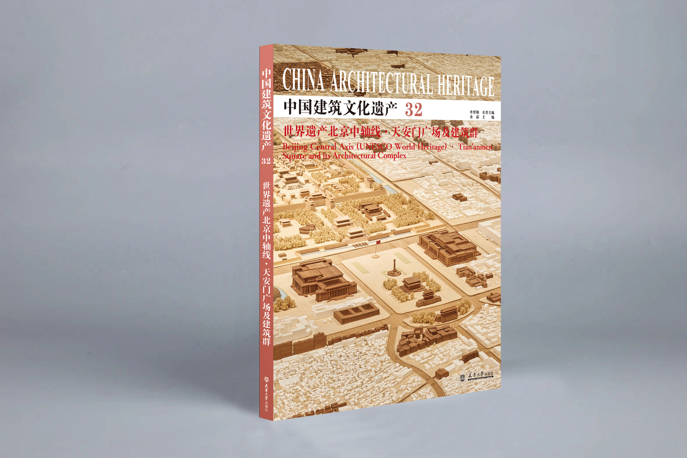
世界遗产北京中轴线·天安门广场及建筑群
单霁翔 名誉主编 金 磊 主 编
北京艺术博物馆文物精华集萃
北京艺术博物馆
长河岸边万寿寺
北京艺术博物馆
2026天大的故事
王杰 张世轶 杜金金
图书热搜榜
图书热销榜
电子技术基础与技能
冯璐 韩艳茹 焦宝玉
1
普通话与职业口语训练
万能
2
建筑CAD
黄瑶
3
固定消防设施
徐方
4
国学经典选读
李清彬
5
直播营销与运营
张蕊, 张磊 ,王冲
6
经济法
李昕一,闫玉苹,李巍,赵妍,牛丽天
7
中国文学典籍英译
刘蕾,耿艳梅,多津玲
8
内燃机原理实验
刘海峰 郑尊清 主编;许之兴 王同金 副主编
9
零基础创建基于Python和Flask的深度学习预测网站
程翔、刘子、严帅、喻庆志、袁海芹
10
2024室内设计论文集
中国建筑学会室内设计分会
11
美术鉴赏
聂涛
12
电子技术基础与技能
冯璐 韩艳茹 焦宝玉
1
普通话与职业口语训练
万能
2
建筑CAD
黄瑶
3
固定消防设施
徐方
4
国学经典选读
李清彬
5
直播营销与运营
张蕊, 张磊 ,王冲
6
经济法
李昕一,闫玉苹,李巍,赵妍,牛丽天
7
中国文学典籍英译
刘蕾,耿艳梅,多津玲
8
内燃机原理实验
刘海峰 郑尊清 主编;许之兴 王同金 副主编
9
零基础创建基于Python和Flask的深度学习预测网站
程翔、刘子、严帅、喻庆志、袁海芹
10
2024室内设计论文集
中国建筑学会室内设计分会
11
美术鉴赏
聂涛
12